Question 8085 – Operating-Systems
December 5, 2023Logical-Reasoning
December 5, 2023Question 9771 – Sequential-Circuits
Consider the following circuit with initial state Q0 = Q1 = 0. The D Flip-flops are positive edged triggered and have set up times 20 nanosecond and hold times 0.
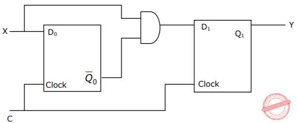
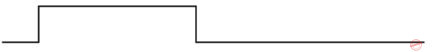
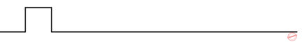
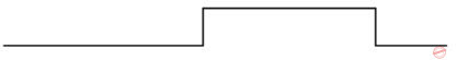
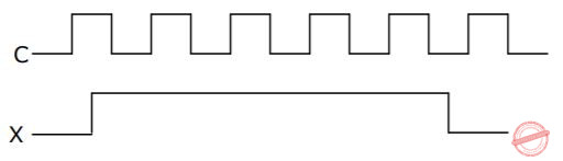
Consider the following timing diagrams of X and C; the clock period of C <= 40 nanosecond. Which one is the correct plot of Y?
Correct Answer: A
Question 4 Explanation:
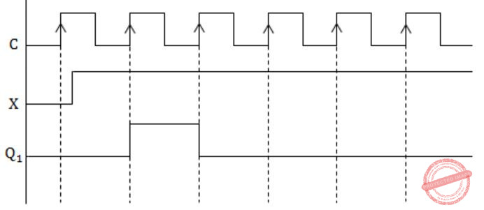
Given clock is +edge triggered.
See the first positive edge. X is 0, and hence the output is 0, because
Y = Q1N = D1×Q0‘ = 0⋅Q0‘ = 0
At second +edge, X is 1 and Q0‘ is also 1. So output is 1 (when second +ve edge of the clock arrives, Q0‘ would surely be 1 because the setup time of flip flop is given as 20ns and clock period is ≥ 40ns).
At third +ve edge, X is 1 and Q0‘ is 0, so output is 0.
Now output never changes back to 1 as Q0‘ is always 0 and when Q0‘ finally becomes 1, X is 0.
Hence option (A) is the correct answer.