Digital-Logic-Design
October 15, 2023Digital-Logic-Design
October 15, 2023Digital-Logic-Design
|
Question 227
|
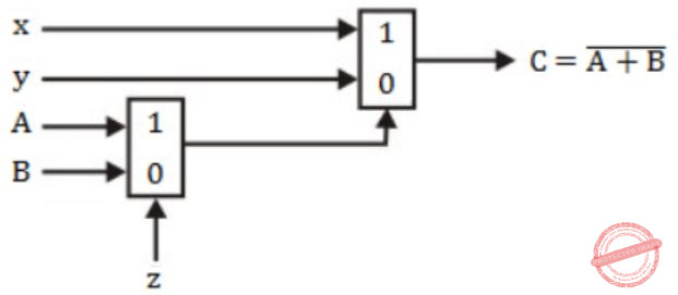
The circuit shown below implements a 2-input NOR gate using two 2-4 MUX (control signal 1 selects the upper input). What are the values of signals x, y and z?
|
1, 0, B
|
|
|
1, 0, A
|
|
|
0, 1, B
|
|
|
0, 1, A
|
Question 227 Explanation:
In MUX1, the equation is
g = Ax + Bz’
In MUX2, the equation is
f = xg + yg’
= x(Az+Bz’) + y(Az+Bz’)’
Function f should be equal to (A+B)’.
Just try to put the values of option (D), i.e., x=0, y=1, z=A,
f = 0(AA+BA’) +1(AA+BA’)’
= (A+B)’
∴ Option (D) is correct.
g = Ax + Bz’
In MUX2, the equation is
f = xg + yg’
= x(Az+Bz’) + y(Az+Bz’)’
Function f should be equal to (A+B)’.
Just try to put the values of option (D), i.e., x=0, y=1, z=A,
f = 0(AA+BA’) +1(AA+BA’)’
= (A+B)’
∴ Option (D) is correct.
Correct Answer: D
Question 227 Explanation:
In MUX1, the equation is
g = Ax + Bz’
In MUX2, the equation is
f = xg + yg’
= x(Az+Bz’) + y(Az+Bz’)’
Function f should be equal to (A+B)’.
Just try to put the values of option (D), i.e., x=0, y=1, z=A,
f = 0(AA+BA’) +1(AA+BA’)’
= (A+B)’
∴ Option (D) is correct.
g = Ax + Bz’
In MUX2, the equation is
f = xg + yg’
= x(Az+Bz’) + y(Az+Bz’)’
Function f should be equal to (A+B)’.
Just try to put the values of option (D), i.e., x=0, y=1, z=A,
f = 0(AA+BA’) +1(AA+BA’)’
= (A+B)’
∴ Option (D) is correct.