Data-Communication
Question 1 |
If the period of a signal is 100 ms. Then its frequency in Hertz is___
10 | |
100 | |
1000 | |
10000 |
Question 1 Explanation:
Given data,
Frequency = 1/Period.
Frequency = 1/100 x 10-3 Hz
= 10 Hz
Frequency = 1/Period.
Frequency = 1/100 x 10-3 Hz
= 10 Hz
Question 2 |
A solution for the differential equation x'(t) + 2x(t) = δ (t) with initial condition x(~0)=0
e -2t u(t) | |
e 2t u(t) | |
e -t u(t) | |
e t u(t) |
Question 3 |
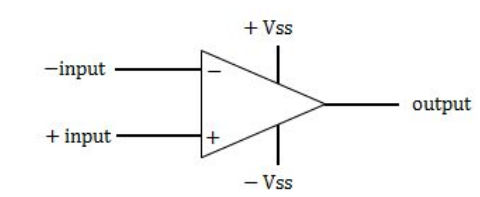
An ideal op-amp is an ideal
Voltage controlled current source | |
voltage controlled voltage source | |
current controlled current source | |
current controlled voltage source |
Question 3 Explanation:
An ideal op-amp lead us to an op-amp with input resistance is infinite, so no current flows into either input terminal (the “current rule”) and that the differential input offset voltage is zero (the “voltage rule”).
Ideal operational amplification will have
➝ High input impedance ( R in = ∞ ) and low output impedance ( R out = 0 )

➝ R in = ∞ , so zero input current
➝ Infinite voltage gain
➝ So, it is a voltage controlled voltage source device.
Ideal operational amplification will have
➝ High input impedance ( R in = ∞ ) and low output impedance ( R out = 0 )

➝ R in = ∞ , so zero input current
➝ Infinite voltage gain
➝ So, it is a voltage controlled voltage source device.
Question 4 |
The open loop transfer function of a feedback control system is G(s).H(s)=1/(S+1) 3 . The gain margin of the system is
2 | |
4 | |
8 | |
16 |
Question 4 Explanation:
Given data,
The open loop transfer function of a feedback control system is G(s).H(s)=1/(S+1) 3
Gain margin=?
→ Here, the formula is -3tan -1 (W pc ) = -180 0
tan -1 (W pc ) = -180 0 /3
= -60 0
W pc =√3 rad/sec
G(s).H(s)=1/(S+1) 3
|G(s).H(s)|=X= 1/(1+W pc 2 )
=1⁄8
G(s).H(s)=1/X
= 8
The open loop transfer function of a feedback control system is G(s).H(s)=1/(S+1) 3
Gain margin=?
→ Here, the formula is -3tan -1 (W pc ) = -180 0
tan -1 (W pc ) = -180 0 /3
= -60 0
W pc =√3 rad/sec
G(s).H(s)=1/(S+1) 3
|G(s).H(s)|=X= 1/(1+W pc 2 )
=1⁄8
G(s).H(s)=1/X
= 8
Question 5 |
If the number of bits per sample in a PCM system is increased from a n to n+1, the improvement in signal to quantization noise ratio will be
3dB | |
6db | |
2n dB | |
n dB |
Question 5 Explanation:
(S/N q)dB
= (1.76 + 6 n) dB
(SQNR) 1 = 1 .76 + 6 n
(SQNR) 2 = 1 .76 + 6 n(n + 1 ) = 1 .76 + 6 n + 6
(SQNR) 2 − (SQNR) 1 = 1 .76 + 6 n + 6 − 1 .76 − 6 n = 6 dB
So for every one bit increase in bits per sample will result is 6 dB improvement in signal to quantization ratio.
= (1.76 + 6 n) dB
(SQNR) 1 = 1 .76 + 6 n
(SQNR) 2 = 1 .76 + 6 n(n + 1 ) = 1 .76 + 6 n + 6
(SQNR) 2 − (SQNR) 1 = 1 .76 + 6 n + 6 − 1 .76 − 6 n = 6 dB
So for every one bit increase in bits per sample will result is 6 dB improvement in signal to quantization ratio.
Question 6 |
A carrier A c Cos(w C )t is frequency modulated by a signal E m Cos(w m )t. The modulation index is m f . the expression for the resulting FM signal is
A c, Cos[w c t+ m f Sin(w m )t] | |
A c Cos[w c t+ m f Cos(w m )t] | |
A c Cos[w c t+ π m f Sin w m t] | |
A c Cos[w c t+ 2 π m f E m Cos(w m )t/w m ] |
Question 6 Explanation:

Question 7 |
The final value theorem is used to find the
Steady state value of the system output | |
Initial value of the system output | |
Transient behaviour of the system output | |
None of these |
Question 7 Explanation:
The final value theorem is used to find the steady state value of the system output
Question 8 |
For the discrete signal x[n]=a n u[n], a>0 the z-transform is
(z+a)/z | |
(z-a)/z | |
z/(z-a) | |
z/(z+a) |
Question 8 Explanation:
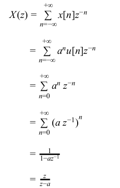
Let x[n] be causal signal given by x[n] = a n u[n]
→ The Z-Transform of x[n] is given by

The ROC is defined by | az −1 | < 1 or | z| > | a| .
Region of Convergence(RoC)
Region of Convergence for a discrete time signal x[n] is dened as a continuous region in z plane where the Z-Transform converges. In order to determine RoC, it is convenient to represent the Z-Transform as a is rational X(z)=P(z)/Q(z)
1. The roots of the equation P(z) = 0 correspond to the ’zeros’ of X(z)
2. The roots of the equation Q(z) = 0 correspond to the ’poles’ of X(z)
3. The RoC of the Z-transform depends on the convergence of the polynomials P(z) and Q(z).
→ The Z-Transform of x[n] is given by

The ROC is defined by | az −1 | < 1 or | z| > | a| .
Region of Convergence(RoC)
Region of Convergence for a discrete time signal x[n] is dened as a continuous region in z plane where the Z-Transform converges. In order to determine RoC, it is convenient to represent the Z-Transform as a is rational X(z)=P(z)/Q(z)
1. The roots of the equation P(z) = 0 correspond to the ’zeros’ of X(z)
2. The roots of the equation Q(z) = 0 correspond to the ’poles’ of X(z)
3. The RoC of the Z-transform depends on the convergence of the polynomials P(z) and Q(z).
Question 9 |
For a periodic signal v(t)=30 sin 100t+10cos 300t +6 sin (500t + π /4), the fundamental frequency in rad/s
100 | |
300 | |
500 | |
None of the above |
Question 9 Explanation:
Given, the signal
V (t) = 3 0 sin 100t + 10 cos 300t + 6 sin (500t + π/4)
So, we have
ω 1 = 100 rads
ω 2 = 300 rads
ω 3 = 500 rads
∴ The respective time periods are
T 1 = 2π/ω1 = 2π/100 sec
T 2 = 2π/ω2 = 2π/300 sec
T 3 = 2π/ω3 = 2π/500 sec
So, the fundamental time period of the signal is
LCM (T 1 , T 2 , T 3 ) =LCM (2π,2π,2π)/HCF (100,300,500)
as T 0 =2π/100
∴ The fundamental frequency, ω0 =2π/T 0 = 100 rad/s
Question 10 |
Twelve 1 Ω resistances are used as edges to form a cube. The resistance between two diagonally opposite corners of the cube is
5/6 Ω | |
1/6 Ω | |
6/5 Ω | |
3/2 Ω |
Question 10 Explanation:

There are 10 questions to complete.
